Description
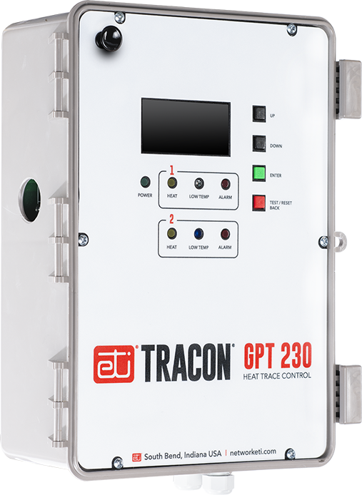
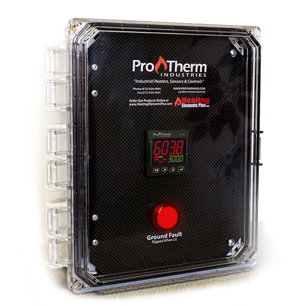
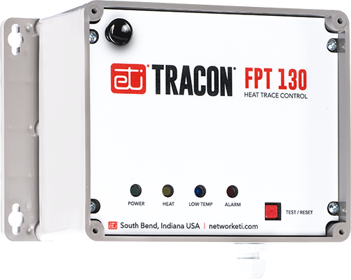
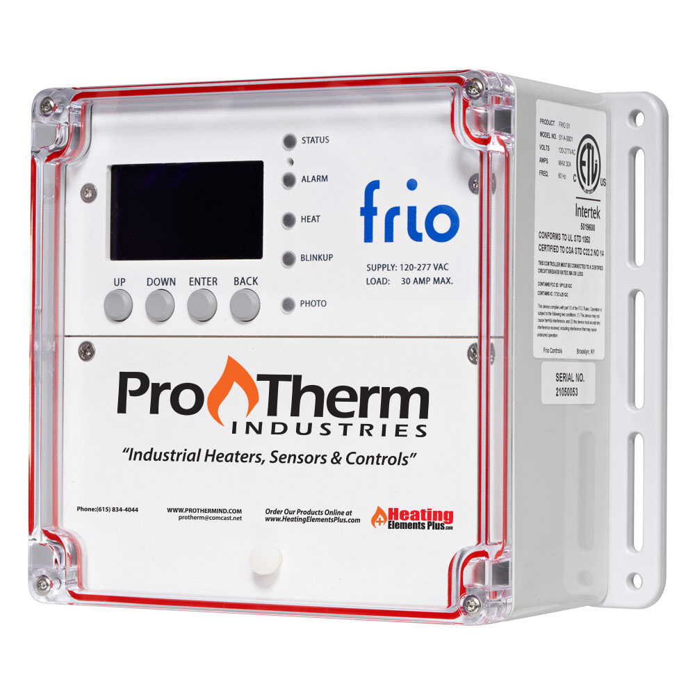
The GPT 230 Dual Channel Heat–Trace Control is a dual–point microprocessor–based heat–trace control thermostat. It is ideal for applications which require two independent heater–control Channels with Ground–Fault Equipment Protection (GFEP). Ideal uses include freeze protection, hot water temperature maintenance, grease line trace, tank heating, and other temperature monitoring and control applications.
The GPT 230 Heat–Trace Control operates from the heater’s power source. A universal power supply allows the GPT 230 to operate from 100 V ac to 277 V ac. It can independently or jointly control two resistive loads up to 30 amps each.
Adjustable Temperature Setpoint and Alarms
The temperature setpoints are adjustable from −99.9°F to 999°F (−73.3°C to 537.7°C) to a tenth degree resolution.
Sensor Inputs
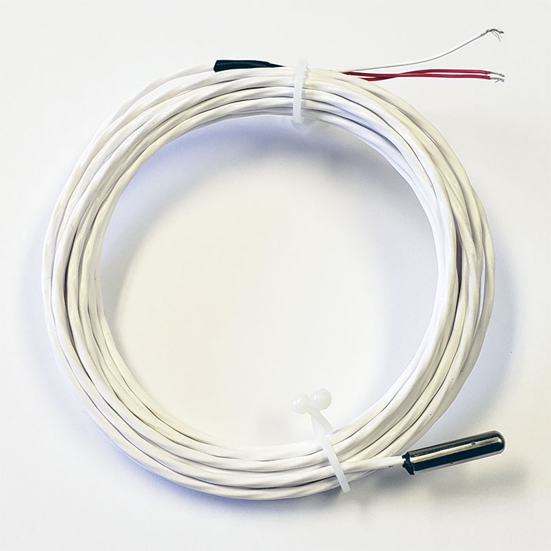
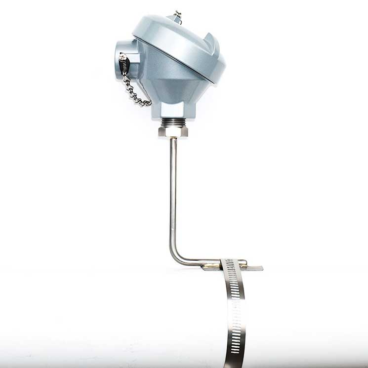
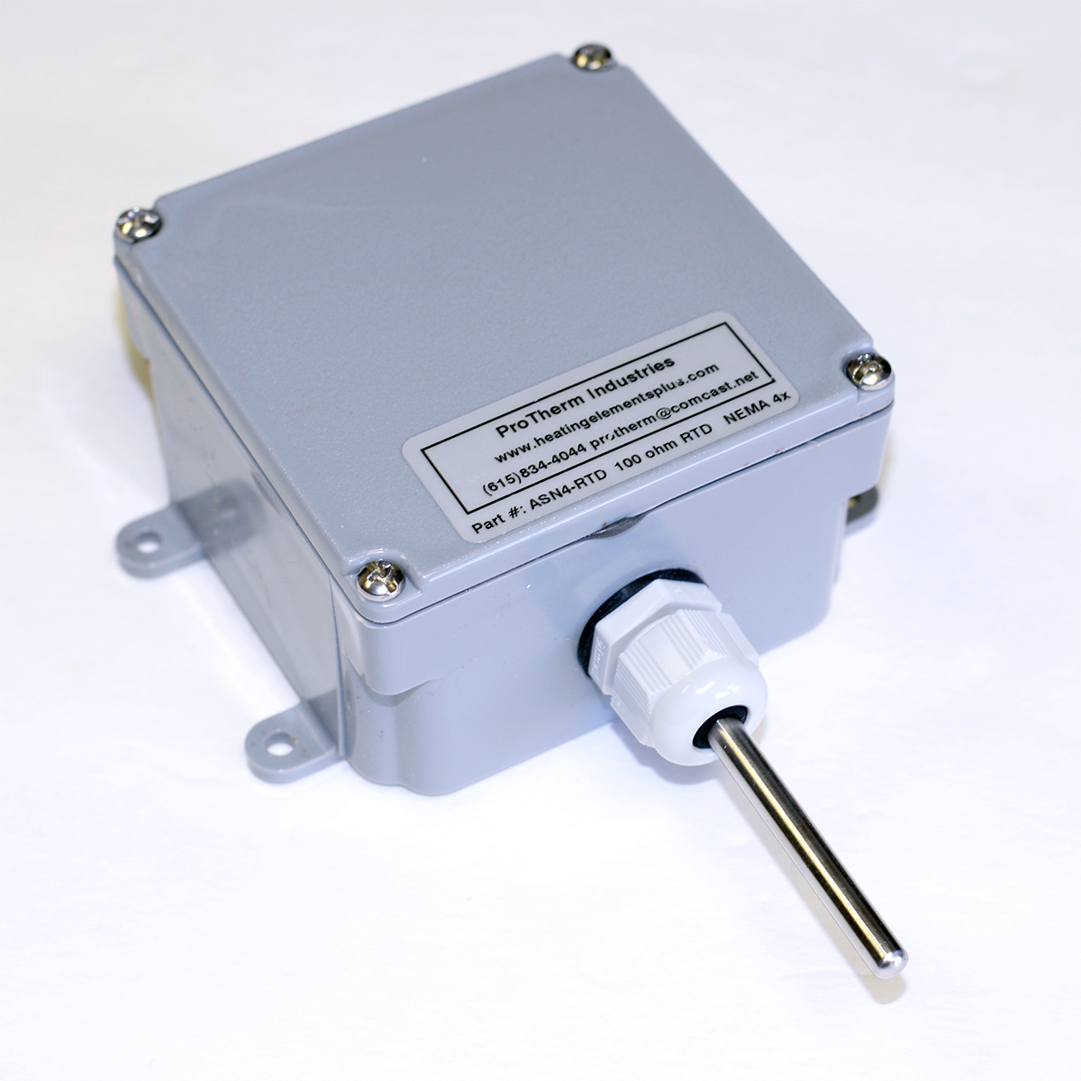
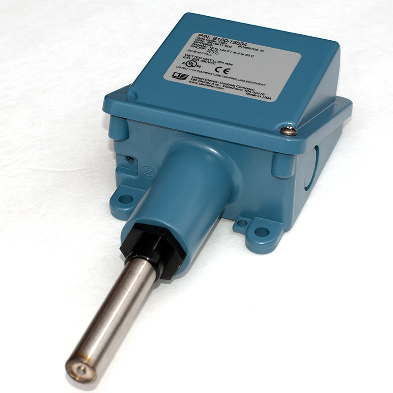
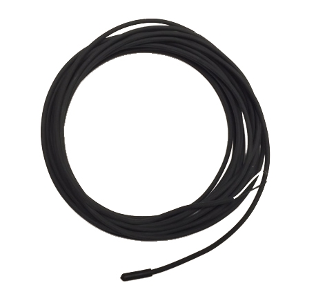
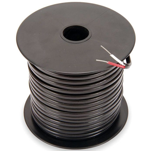
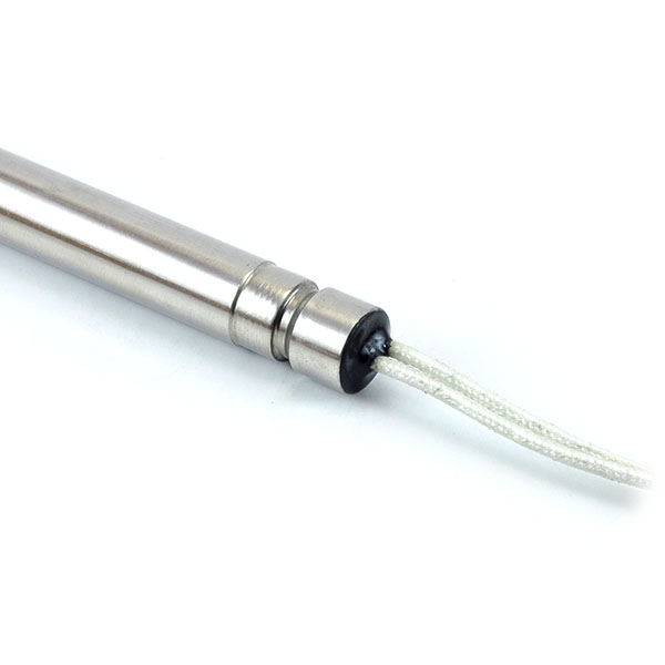
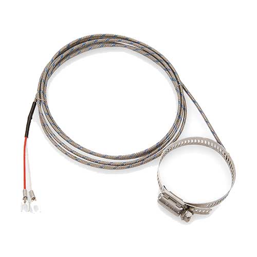
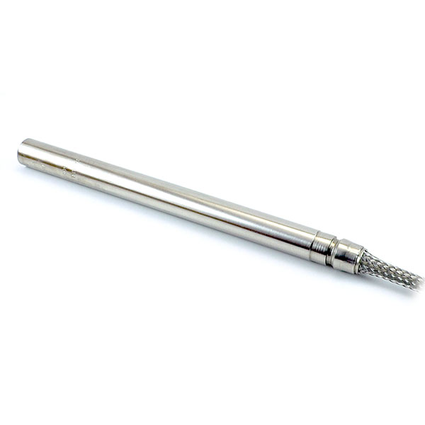
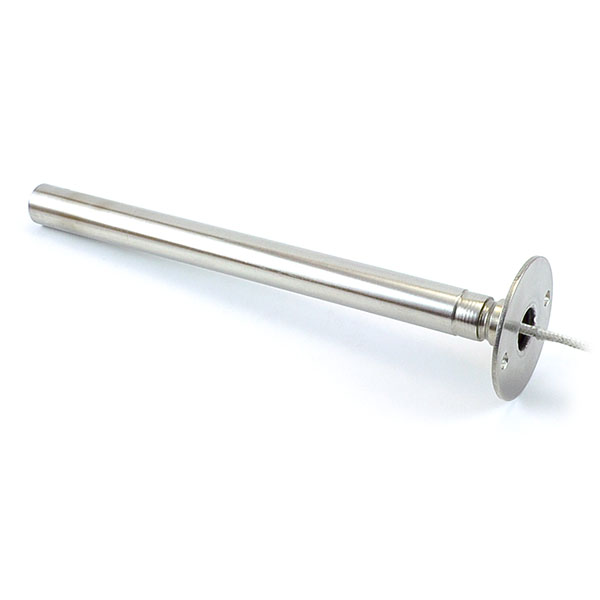
The GPT 230 comes with two 100K ohm thermistor temperature sensors with 20 ft. jacketed cables. The included sensors have an operating range of −40°F to 230°F (−40°C to 110°C). The GPT 230 can also use 2–, 3–, or 4–wire RTD sensors for systems requiring high–temperature sensing. Two temperature sensor inputs are provided, and the channels can operate independently or from one sensor.
Precision Monitoring and Control
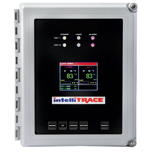
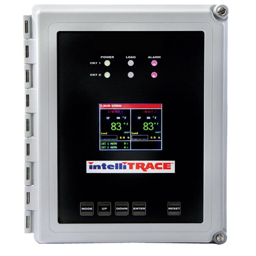
The GPT 230 monitors temperature, load current, and ground leakage current. Alarms include high temperature, low temperature, high load current, low load current, ground fault, sensor fault, internal fault, and power fail. These alarms are easy to adjust and observe from the front panel. The GPT 230 can be set to energize or de-energize the heaters during a sensor fault.
Ground–Fault Equipment Protection
The GPT 230 Heat–Trace Control includes integral GFEP for each channel. This eliminates the extra expenses associated with having to provide separate GFEP components in the circuit panel. The GPT 230 normally disconnects power immediately to the affected zone when ground fault current exceeds the set value. But if it is set to Fire Protect mode, for critical fire protection systems, then it will generate the alarm but power will be maintained to prevent freezing.
Automatic GFEP Circuit Self–Test
To ensure continued safe operation, the GPT 230 performs a self–test of the GFEP circuits when power is first applied, along with a load ground fault test, and this repeats periodically thereafter at an adjustable interval.
For complete information describing its application, installation, and features, please contact Customer Service.
Specifications
| General | |
|---|---|
| Certifications | UL 60730–1, UL 1053, CSA E60730–1:13 |
| Environmental | |
|---|---|
| Area Of Use | Nonhazardous Locations |
| Operating Temperature Range | −40°F to 122°F (−40°C to 50°C) |
| Enclosure | |
|---|---|
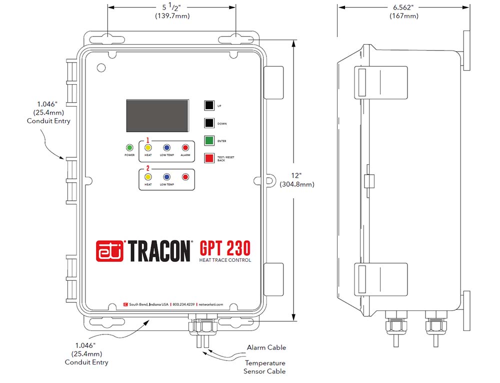
| Dimensions | 9.0″ (W) 12 4/5″ x (H) x 5 9/10″ (D) 229 mm (W) x 325 mm (H) x 150 mm (D) |
| Protection | NEMA 4X, IP66 |
| Cover Attachment | Polycarbonate cover |
| Cable Entries | Two liquid-tight cable glands installed for Two liquid-tight cable glands installed for sensor and alarm leads, cable diameter 0.08” to 0.24” (2 mm to 6 mm)
Two 1.046″ holes to accommodate ¾” conduit fittings for power wiring connections |
| Material | Polycarbonate |
| Weight | 5.8 lb. (2.63 kg) |
| Mounting | Wall mount with flanges |
| Wiring Terminal Ratings | |
|---|---|
| Power | Barrier Strip Terminals for Line, Neutral, and Ground; use 10 AWG wires rated for at least 194°F (90°C) |
| Sensors | Terminal Block, rising cage clamp, 12–28 AWG leads |
| Alarm Relay | Terminal Block, rising cage clamp, 12–28 AWG leads |
| User Interfaces | |
|---|---|
| Pushbuttons | UP, DOWN, ENTER, TEST / RESET BACK |
| DIP Switches | RTD wiring configuration Panel lockout |
| Parameter Settings For Each Zone | |
|---|---|
| Temperature Setpoint Heat ON | Adjustable −99.9°F to 999°F (−73.3°C to 537.7°C) |
| Temperature Setpoint Heat OFF | Adjustable −99.9°F to 999°F (−73.3°C to 537.7°C) |
| Low–Temperature Alarm Threshold | −99.9°F to 999°F (−73.3°C to 537.7°C) Default 35°F (−1.7°C) |
| Low–Temperature Alarm Delay | 0 s to 3000 s 0 s to 3000 s Default 300 s |
| High–Temperature Alarm Threshold | −99.9°F to 999°F (−73.3°C to 537.7°C) Default 140°F (60°C) |
| High–Temperature Alarm Delay | 0 s to 3000 s Default 300 s |
| Low–Current Alarm Threshold | 0.0 A to 10.0 A Default 0.1 A |
| Low–Current Alarm Delay | 0 s to 300 s Default 5 s |
| High–Current Alarm Threshold | 0.0 A to 55.0 A Default 30.0 A |
| High–Current Alarm Delay | 0 s to 600 s Default 300 s |
| Ground Fault Limit Current | 1.0 mA to 300.0 mA Default 30 mA |
| Self–Test Interval | 1 h to 250 h when enabled Default 24 h |
| Temperature Unit | °F or° C Default°F |
| Indicators | |
|---|---|
| Status Indicator | Power (Green) Heater (Yellow) Low Temperature (Blue) Summary Alarm (Red) |
| Display | 27″ OLED graphic 128×64 |
| Summary Alarm Relay Reporting | Low temperature High temperature Low load current High load current High ground fault current Stuck relay Sensor fault Internal fault |
| Control Ratings | |
| Temperature Accuracy | +/− 2°F (1°C) |
| Temperature Sensors | |
| Temperature Inputs | (Included) Two Thermistors: 100k ohms at 25°C, range −40°F to 230°F (−40°C to 110°C), 20ft Lead (25076)RTD Sensor: Platinum, Alpha = 0.00385, ITS–90, 100 ohms at 0°CInput supports 2–wire, 3–wire, or 4–wire connection Sensor operates at 1 mA |
| (GFEP) Ground–Fault Equipment Protection | |
| Range | Adjustable 1mA to 300 mA Default 30 mA +/- 2% |
| Automatic Self Test | Verifies GFEP functionality every 24 hr., when the load is turned on, and when there is a load supplied |
| Power | |
| Supply Voltage | 100 – 277 V ac 50/60 Hz |
| Controller Power Consumption | 5 W maximum, 2 W idle |
| Load Rating | 30 A, 100 – 277 V ac resistive |

